| Up | Main | Arduino | One | Two | Three | Four | Notes |
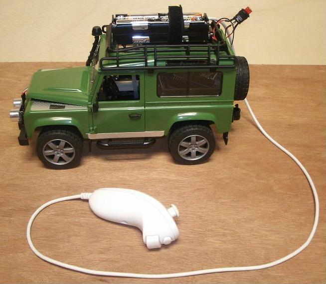
This page documents my efforts to control a small toy car, in this case a Land Rover Defender, using an Arduino Uno board. After some initial work taking the toy car apart a drive motor, a steering servo, an indicator light, an ultrasonic ranging sensor, and a horn were added. The car is controlled by a Wii nunchuck controller, or can be programmed to run autonomously.
|
|
The following table provides a bill of material for reference. Some of the parts were on hand, so finding an exact match isn't always possible.
| Component | Description | Price | Source |
|---|---|---|---|
| Car | Bruder Land Rover Defender | $27 | Amazon |
| Drive Motor | 6V DC motor | $0 | Salvaged |
| Steering Servo | Virtuabotix SG90 9 gram micro-servo | $6 | Amazon |
| On Off Switch | Illuminated pushbotton with red LED | $2.19 | RadioShack |
| Logic Board | Arduino Uno R3 | $23.50 | Amazon |
| Motor Controller | Arduino Motor Shield | $35 | RadioShack |
| Sensor | HC-SR04 Ultrasonic Distance Sensor | $4.40 | Amazon |
| Connector | Wiichuck Wii nunchuck adapter | $4 | Seeed Studio |
| Remote | Wii nunchuck | $18 | Amazon |
| Buzzer | 75dB Piezo Electric Buzzer | $3.59 | RadioShack |
The Arduino boards use Atmel AVR processors. The Uno board has the ATmega328 in a 28-pin PDIP package. These are 8-bit processors and run at 16MHz. The board runs off a USB connection at 5V or from a DC power source from 7V to 12V. There are 19 IO ports and 1 LED (in addition to a power LED). Multiple suppliers carry these boards or variations.
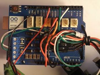
Because these boards can't support the power requirements of motors, another board is mated to the top of the Uno board. The Arduino project provides a motor controller called the Motor Shield. This board can provide 2A per channel, supports a free run and a brake function, and current sensing. It mates to the top of the Uno board by long pins that slide into the connectors. Several holes in the shield line up with holes in the Uno to allow bolts or ties to keep the boards together.
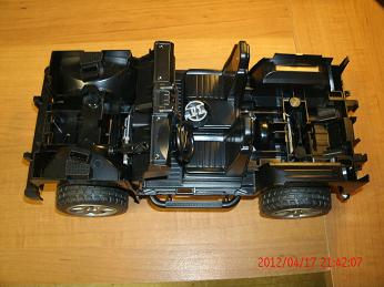
The first step was to take apart the toy car so a drive motor and steering motor could be added. To make this easier a toy car was selected that already had front wheel steering. In fact, not only do the front wheels turn but there is a small knob on the console between the front seats which is used to steer the car. This made adding a servo motor very easy.
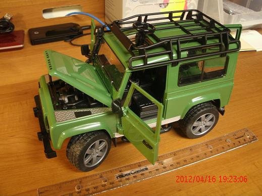
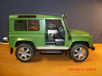
In the picture below the sun roof is open and the steering extender which came with the car is in place. This is what the small knob between the front seats was made for. The car is a 1/16th scale Bruder Land Rover Defender station wagon, item number 02590. It's about 11 inches long and five inches wide. Several small tabs had to be cut away with a small knife to remove the chassis.
|
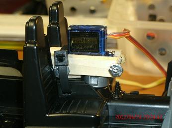
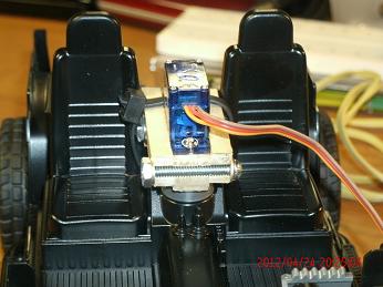
Once the chassis was removed from the frame, adding a micro servo motor was easy. The center hole in the gray knob was enlarged to fit the gear of the servo. Some small wood was bolted around the servo as a bracket. A small hole was drilled into the center console for a tie strap.
|
|
|
|
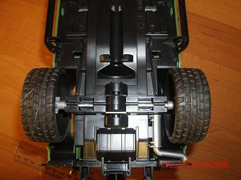
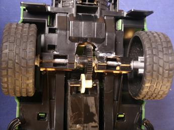
The next step was much harder. One of the rear wheels was removed from the axle by slicing the hub, but not destroying it since we need to put it back on. Then a lot of plastic was removed from the frame with a small grinder, small knife, and file. The drive motor was originally from an exercise machine and came with gears. One gear is attached to the axle with washers and a glue gun. This broke free after some use so the washers were soldered and more glue was added. So far it's holding up. For the next toy car project a Tamiya motor with gears looks promising. And at $8 it would be worth it considering the time this one took.
|
|
With the two motors in place the Arduino with motor shield was added and some simple initial code tested everything out. Click on either of the following links to see the code. To try this out, right click on the left link and download the source code. The right link is color syntax highlighted so it's easier to read in a browser and to print.
| Arduino Source Code File | Web page view for printing |
The code starts with defining some constants so references can be to PWM_A instead of 3, making the rest of the code much easier to debug. Then some global variables are defined and initialized. The setup() function is called once and performs all initialization. This is a standard Arduino function which is why this code never calls it, the call is handled by the Arduino bootloader. In the setup() function a limited power-on self test is performed with a lot of one and two second delays. These are removed in later verions. The main loop steps through several states one time then stops. This helps fine tune any adjustments, such as in state 5 where the value 95 was used to keep the car going straight instead of 90. Getting the steering servo perfectly aligned so that 90 was straight proved much harder than making a small change in software to compensate.
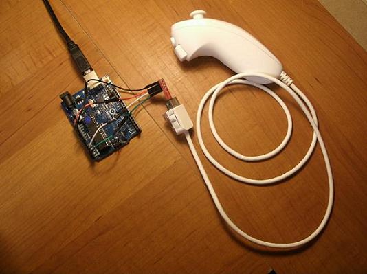
The Wii nunchuck controller is a 2 degree of freedom joystick, with a 3 axis accelerometer and two buttons in a compact plastic hand grip. It is connected to the Wiimote with a cable that ends in a connector which looks like a large USB male connector. A breakout board is available which fits into this connector to provide four pins: VCC, Ground, SDA, and SCL. The wiichuck communicates to the wiimote using I2C, also known as TWI. For a quick introduction see the WikiPedia page.
The wiichuck is a 3.3V part but also works with the Arduino at 5V. An aftermarket wii nunchuck from Nyko, which is less expensive, does not work at 5V. Using jumper wires, connect power to the 3.3V pin and ground to a ground pin.
The hardware reference page for the Arduino Uno board notes that for TWI functionality A4 is the SDA pin and A5 is the SCL. Connect the pin marked 'c' to analog pin 5 and the pin marked 'd' to analog pin 4.
There is sample code at todbot.com but this was developed for an older version of the Arduino code. The following steps work with Arduino version 1.0.1. First make some changes to the Arduino Wire library. This is in the file twi.h in the directory libraries\Wire\utility. Uncomment the line define ATMEGA8. Add the lines which define CPU_FREQ 16000000L. Change the line for define TWI_FREQ 100000L. The new and changed lines at the start of the file should resemble the following.
//uncommented the following #define ATMEGA8 //added the following #ifndef CPU_FREQ #define CPU_FREQ 16000000L #endif #ifndef TWI_FREQ #define TWI_FREQ 100000L #endif |
Now copy the updated code below which was modified from WiichuckDemo.zip found at todbot.com. The file was renamed from .pde to .ino because the file type for Arduino code changed since the todbot.com code was published. All the calls to Wire.send were changed to Wire.write. All the calls to Wire.receive were changed to Wire.read. These are required because of additional changes introduced in Arduino 1.0.
The following code will get data from the nunchuck and print it to the terminal. After downloading this code to the Arduino, open the Serial Monitor under the Tools directory. By moving the nunchuck and joystick you'll observe the maximum and minimum values for each sensor.
|
| Arduino Source Code File |
| Web page view for printing |
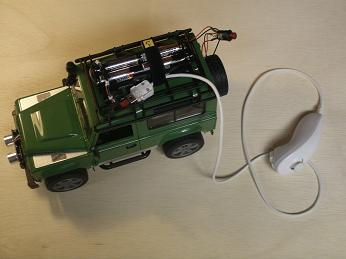
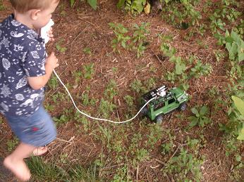
The robot is controlled by a Wii nunchuck using the joystick. A red LED warns of impending collision. The large Z button on the controller sounds a horn. Eight AA batteries provide power.
|
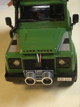
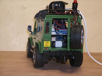
On the joystick left and right steer, while forward and back control drive motor speed and direction. The red LED in the on/off switch blinks every two seconds if nothing is detected within two feet of the robot. At two feet the blink rate increases to once every second. At one foot the rate increases to twice every second. At six inches this goes to ten times every second. The left picture below shows the four wires from the ultrasonic ranging sensor are routed through the empty engine compartment. With some minimal plastic removal the sensor fits into the front bumper in some existing slots for a toy attachment. The right picture shows the horn buzzer beneath the Uno and motor boards, and the mess of wires above.
|
|
The pins on the Arduino are being used as follows. It's important to think this out because some pins are dedicated for specific usage (such as TWI) while others may or may not have PWM capabilities.
|
| IO Pin | Description |
|---|---|
| 0 RX | Not connected. Reserved for TTL serial data. |
| 1 TX | Not connected. Reserved for TTL serial data. |
| 2 | Not Used. External interrupt pin. Available for expansion. |
| 3~ | Channel A - Drive motor PWM. 0=stop, 255=max. |
| 4 | Ultrasonic ranging sensor trigger. |
| 5~ | Steering servo PWM. 90=straight. Connected to TinkerKit orange analog output header on motor shield. |
| 6~ | Not Used or connected. Internally connected to TinkerKit orange analog output on motor shield. |
| 7 | Ultrasonic ranging sensor echo. |
| 8 | Not Used. Channel B brake. |
| 9~ | Channel A Drive motor brake. 0=free spin, 1=brake. |
| 10~ | Connected to + of Red LED in on/off switch. |
| 11~ | Not Used. Channel B PWM. |
| 12 | Channel A Drive motor direction. 1=forward, 0=backward. |
| 13 | Not Used. Channel B direction. Yellow LED on Uno board. |
| GND | Connected to ground of Red LED in on/off switch (-). |
| AREF | Not Used. |
| SDA | Not Used. |
| SCL | Not Used. |
| A5 | Connect to 'c' pin on Wiichuck. Used for clock - SCL. |
| A4 | Connect to 'd' pin on Wiichuck. Used for data - SDA. |
| A3 | Not Used. TinkerKit white analog input on motor shield. |
| A2 | Not Used. TinkerKit white analog input on motor shield. |
| A1 | Not Used - current consumption of channel B motor |
| A0 | Read current consumption of channel a drive motor in software. No wire connected. |
| VIN | Not Used. Board power is from power block on motor shield. |
| GND | Connect to Wii nunchuck ground (-). |
| GND | Ultrasonic sensor ground (GND). |
| 5V | Ultrasonic sensor power (Vcc). |
| 3.3V | Connect to Wii nunchuck power (+). |
| RESET | Not Used. |
| IOREF | Not Used. |
| Unmarked | Not Used. |
| A+ | Blue wire to drive motor. |
| A- | Yellow wire to drive motor. |
Motor Control -- Use analogWrite(pin,value) to generate a PWM wave. After a call to analogWrite() the pin will generate a steady square wave of the specified duty cycle until the next call to analogWrite() or a call to digitalRead() or digitalWrite() on the same pin. The frequency of the PWM signal is approximately 490 Hz. The value is between 0 (always off) and 255 (always on).
Current Consumption -- Measure the current going through the DC motor by reading the A0 pin. The voltage is proportional to the measured current, which can be read as a normal analog input, through the function analogRead(). It is calibrated to be 3.3V when the channel is delivering its maximum possible current (2A).
Steering Servo -- This is a 180 degree servo. After every write wait 10 ms before sending another or the second write will be ignored.
TWI/I2C -- If no device is connected the board will not complete the software initialization using Wire.beginTransmission(). The board will appear to lock up.
The code is thoroughly commented. As in there are more lines of comments than code. It's my experience that a design document independent of the code is seldom read, so it's better to put as much as possible in the source code file.
|
| Arduino Project Zip File |
| Web page view for printing |
An issue which my benchtop testing didn't uncover is occasional loss of control when the ultrasonic ranging sensor times out. The sensor sends multiple chirps then waits for an echo. Occasionally the echo is never detected. By default, the Arduino pulseIn() function will wait up to 1 second then return. When this happens the robot becomes unresponsive for a second. Interrupts are queued, so when control resumes some of the commands are executed quickly while the Arduino catches up.
The solution is to limit waiting for the echo to 3.6 ms, which limits the sensor range to 25 inches.
A horn was also added to take advantage of the additional inputs available on the Wii nunchuck. Initially this was controlled by a PWM output so the volume could be adjusted, however the bottom of the Arduino board near the voltage regulator quickly become hot. Changing this to a digital output seemed to help limit the heat.
While my intent was to add a turret mounted sensor, the heat issue and the limited remaining space inside the rover have made me reconsider.
Hopefully you found this helpful, maybe entertaining, certainly not drudgery. If you have comments or questions post them to the appropriate entry on the related blog site.
| Up | Main | Arduino | One | Two | Three | Four | Notes |